Contact: Bruce
Tel: +86-755-22 666 190
Fax: +86-755-29 043 136
E-mail: sales@ultrasonic-sensors.net
Skype: longsunac
Address: Room A1, 6/F, Bldg. No. 531, Bagua 3rd Road No. 277, Futian District, Shenzhen, China 518029
5. Ultrasonic Application in Rear Parking Aid System
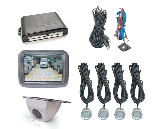
In reality, the ultrasonic is the most common used in rear parking aid system (RPA in short) for car or truck we ever see. Rear parking aid system is also called reversing radar, it consists of controller, display, buzzer and ultrasonic transducer, sometimes including camera (see below figure 2-1):

Figure 2-1
In reverse, helping the driver to see rear-view mirror can not see things, it can use sound or a more intuitive display to inform the driver of the barrier around, lifting the driver’s vision stress from front, rear, right and left angle when parking, reversing and start the vehicle, and help the driver to remove the dead and blurred vision defects, improve the driving safety.
Working principle of RPA (rear parking aid system)
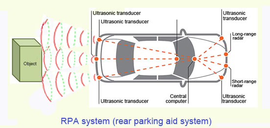
RPA is generally based on the principle of ultrasonic distance measurement (refer to figure 1-1), ultrasonic transducer emits an ultrasonic signal under control of the controller, generates an echo signal when encountering an obstacle, the ultrasonic transducer receives the echo signal which is transmitted to the controller for data processing, and determines the barriers location, shows the distance and give any other warning signal (for example, bibibi...generated by buzzer), so as to achieve the purpose of safe parking (see figure 2-2).

Figure 2-2
Incident angle impact analysis of ultrasonic echo
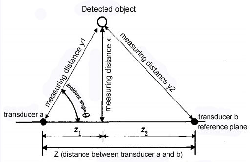
From figure 2-2, we know the detected object is not always right in the middle to car or truck, if the RPA is used to measure the distance between(from) the surface and (to) the point, where there is a geometric angle exists among the measured object, the transducer and the reference plane where the transducer lies in, namely the incident angle forms by the reflected wave and the transducer, when this angle is not 90 °, the distance measured by the RPA is from an obstacle to the transducer (i.e, y1 or y2), not the distance(i.e, x) from the measured object to the reference plane, which will result in measurement error, as shown in Fig 2-3.

Incident angle impact analysis chart
Figure 2-3
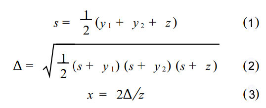
When the distance to the obstacle is small, the error will become the main source of error for close distance. Therefore, how can we exactly calculate the distance between obstacle and car in practice under such situation ? We can use two or over transducers to measure the distance simultaneously, and calculate the actual distance through the geometric relationship between them in order to eliminate such errors. Here is the formula as follows see figure 2-4:

Figure 2-4
Note: y1, y2 is the distance from transducer a or b to the detected object;
z is the distance from transducer a to transducer b;
x is the distance from the detected object to reference plane surface.


